
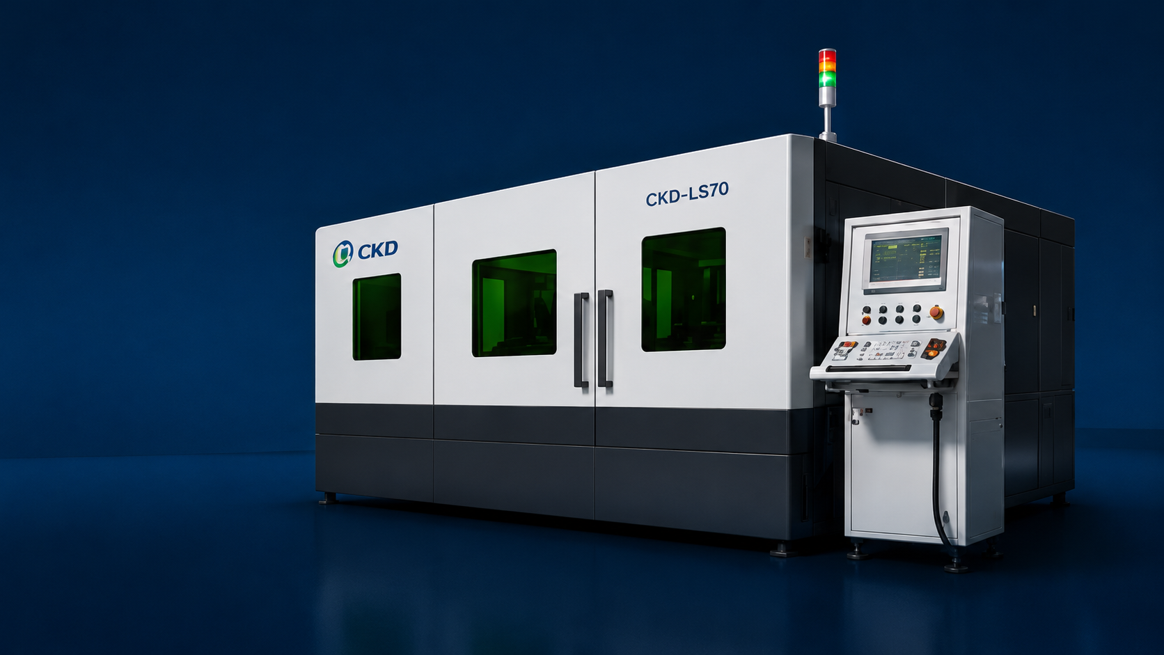
CKD precision laser system prepared for application validation

Application engineering

Start with the part, not the catalogue.

A useful machine recommendation begins with the material, target area, defect limit, output target and line interface. This page shows what CKD needs before sample validation starts.

Part and materialPackage, substrate, resin or glass condition.
Quality boundaryTarget zone, protected surface, chipping or residue limit.
Production targetTakt time, UPH, batch size and changeover frequency.
Line interfaceLoading, recipe control, marking and upstream/downstream equipment.

Required application inputs

Two processes need two different data sets.

The homepage explains the machine families. The engineering review begins one level deeper: the actual part and the condition that must be protected.

Laser deflashing / glue removal

Define what must be removed and what must remain untouched.

  • PackageSMD or through-hole format, strip layout, A/B face and orientation.
  • ResidueEpoxy, silicone, UV glue or other layer; colour and estimated thickness.
  • Protected areaCeramic body, electrode, coating, lead root or electrical-value constraint.
  • AutomationFeed method, flip requirement, barcode recipe and optional marking.
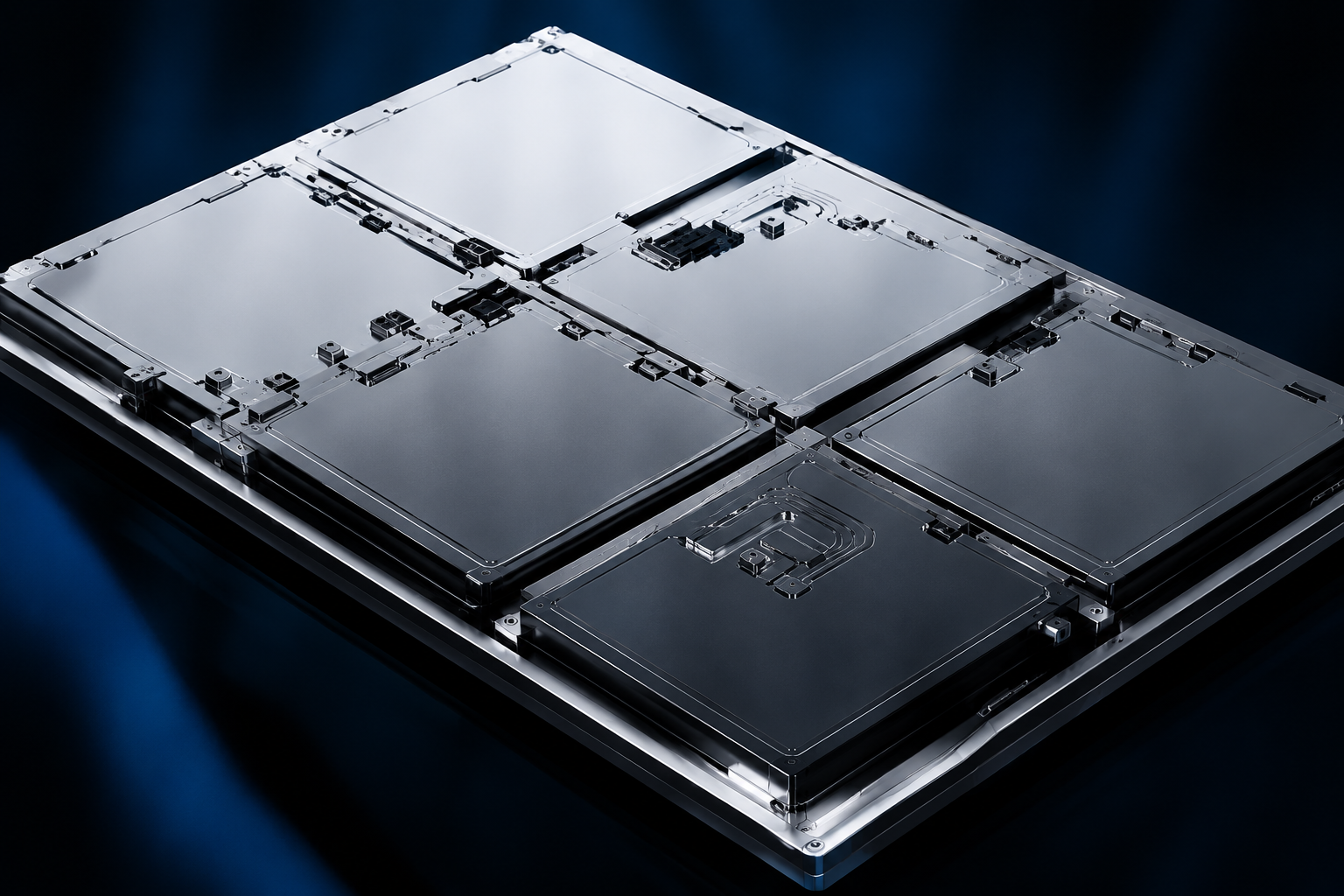
Picosecond brittle-material cutting

Define the material condition and the separation route.

  • MaterialGlass, sapphire, ceramic or crystal; strengthened state and internal quality.
  • GeometryThickness, drawing, contour, apertures, Mark points and usable panel area.
  • Edge targetChipping, taper, roughness, strength and downstream bonding requirement.
  • SeparationSelf-release, CO2 thermal separation, mechanical, ultrasonic or chemical route.

Sample-to-recipe path

A machine configuration follows a validated process window.

01

Lock the input

Record material lot, part drawing, target area, protected surfaces and acceptance limit.

02

Run the optical trial

Screen wavelength, energy, scan path or filament spacing against the real sample.

03

Confirm the window

Compare residue, edge condition, thermal influence, repeatability and takt time.

04

Define the cell

Freeze loading, vision, recipe control, safety, extraction and line-interface requirements.

Process logic

The removal step and the cutting step solve different failure modes.

These routes are selected by material response, not by a generic product label.

Electronic component prepared for selective laser removal

Selective removal

Vision-guided scanning keeps tools away from the part.

The training material describes non-contact removal for epoxy, silicone and UV glue, including curved end faces and lead-root areas that mechanical tools cannot reach consistently. Recipe control can also support A/B-face processing and barcode job loading.

Brittle glass prepared for picosecond laser cutting

Filamentation + separation

Cutting and separation are reviewed as one process.

The source material separates filament formation from the downstream release method. Non-strengthened glass may use CO2 thermal stress; strengthened glass can release through its own stored stress; LCD, filter and camera glass may require mechanical, ultrasonic, laser or chemical separation depending on the part.

Site-readiness review

Confirm utilities and environment before the layout is frozen.

Review itemDeflashing / glue removalBrittle-material cutting
Sample packageRepresentative strips, resin details, protected-zone drawing and electrical acceptance criteria.Representative material lots, CAD/DXF, strengthening state, edge target and selected separation route.
UtilitiesClean dry air and extraction are part of the review; final power and exhaust values follow the selected configuration.Power, cooling/extraction, vacuum holding and floor loading are confirmed against platform size and laser configuration.
EnvironmentStable temperature and controlled dust protect repeatability; limits are confirmed on the final equipment sheet.Training references 20–30°C, ±1.5°C stability and below 50% RH at 25°C for the picosecond laser environment.
IntegrationFeed, flip, recipe, barcode, marking, MES and downstream inspection signals.Panel loading, vision marks, motion file, separation station and outgoing handling.

Reference basis: CKD deflashing and brittle-material training files in the customer folder. Final values remain subject to the selected machine, material test and agreed scope.

Send one representative part package.

Include the drawing, material condition, current defect, target quality, takt time and required line interface. CKD can then define the sample plan and configuration review.

Start an application review